Alex Singer ·
Open-source static timing analysis for FPGAs
The open-source Logik FPGA toolchain has just become a lot more powerful!
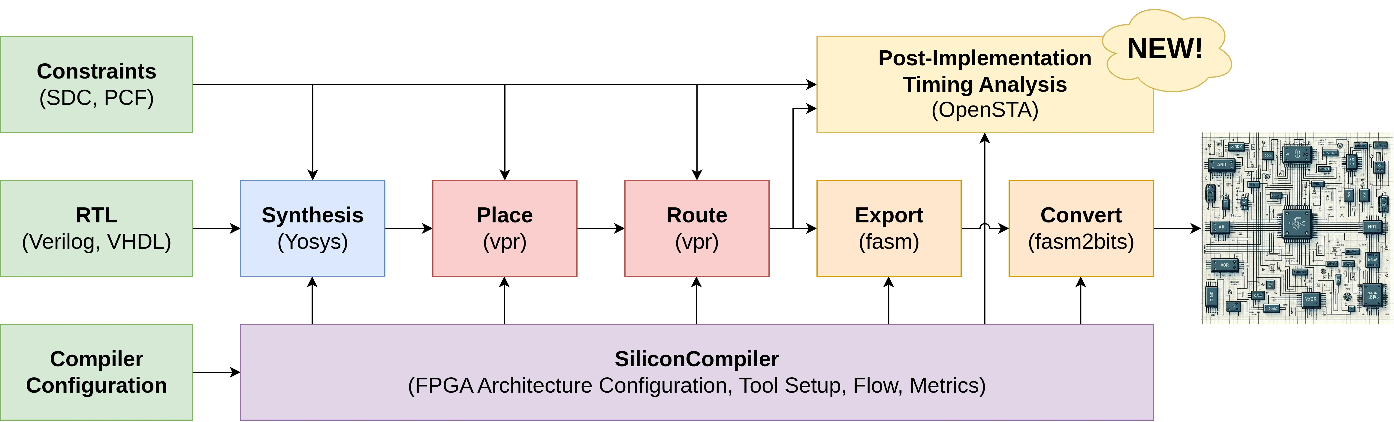
The Logik toolchain is a collection of completely open-source software components, including Yosys for synthesis, VPR for Place and Route, genfasm for bitstream exporting, and Silicon Compiler to orchestrate the flow. Today, we’re adding a powerful new member to that lineup: OpenSTA, for post-implementation static timing analysis.
Historically, OpenSTA has been a tool for ASIC static timing analysis. However, we’ve made key improvements to how VPR emits its netlist and timing graph, allowing us to connect VPR’s placed and routed solution directly to OpenSTA. This brings open-source FPGA timing analysis up to the level of ASICs, opening up new avenues for collaboration.
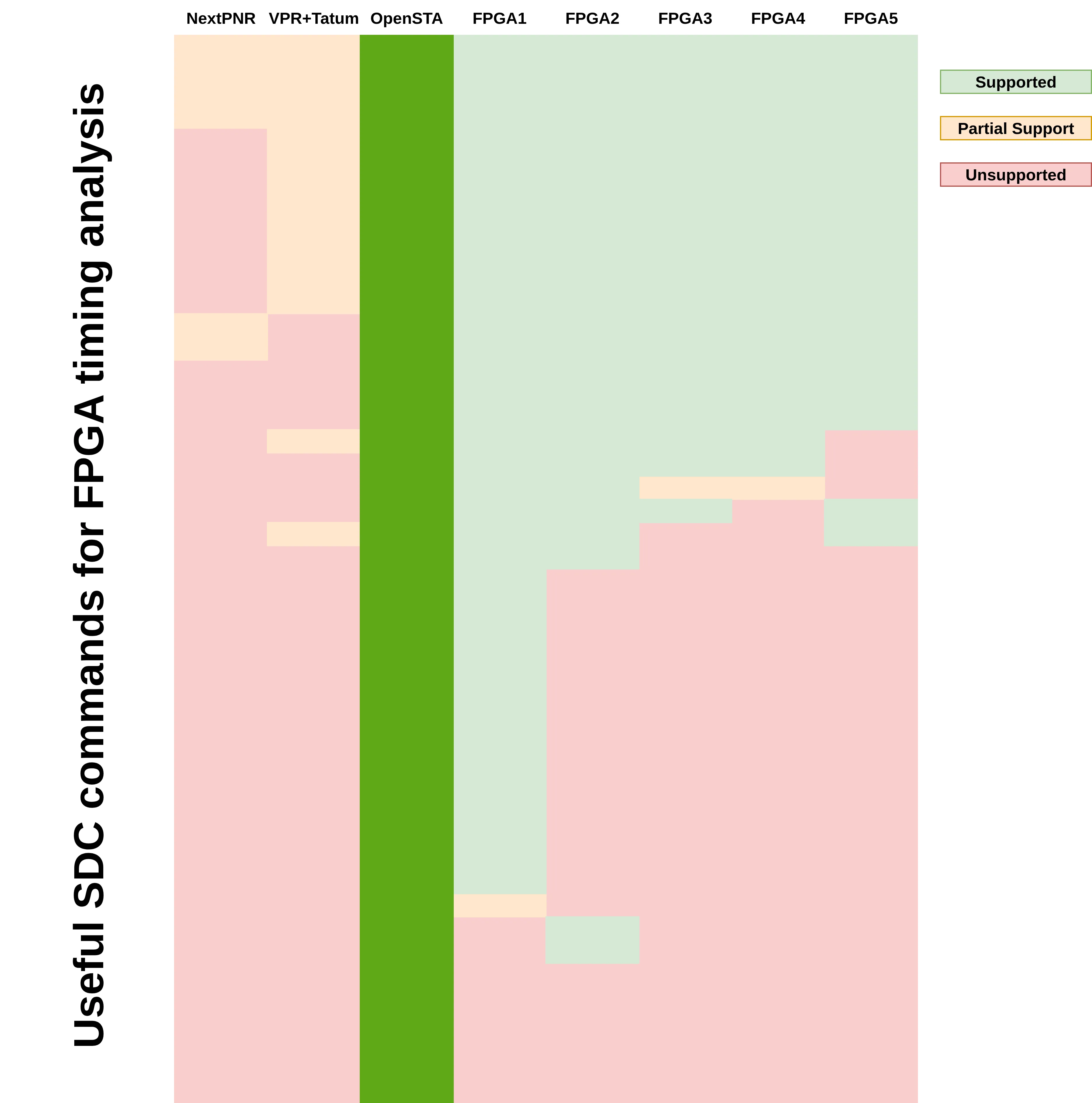
Traditionally, open-source FPGA timing analysis has been performed by tools integrated directly into the place and route step. For example, VPR performs timing analysis using the Tatum timing analyzer, which is a powerful tool. However, because this analysis is a behind-the-scenes part of the place and route process, it lacks features expected from commercial timing analyzers. It doesn’t provide a comprehensive user interface and has only basic SDC support, limiting your ability to interact with the analysis.
By integrating with OpenSTA, our flow now provides a separate, post-implementation timing analysis step. This allows for final timing validation as an independent process, giving you the ability to interact directly with a comprehensive user interface. This shift from an integrated, “behind-the-scenes” process to an offline, user-driven one provides you with both greater control and more robust features, ensuring the placed and routed circuit meets your timing constraints with a level of confidence not previously available in open-source FPGA flows.
Compared to all other open-source and commercial timing analyzers, OpenSTA provides the most comprehensive support for SDC commands, especially those that are particularly useful for FPGA timing analysis. This enables the Logik flow to accept a larger set of timing constraints, which can allow for more accurate timing analysis.
Since OpenSTA uses a TCL interface, our flow has much more granular and robust control over the timing analysis compared to VPR. Also, by setting a Silicon Compiler breakpoint at the timing step of the flow, you will be dropped into an interactive TCL interface, allowing even finer control over the timing analysis, beyond what the Logik flow does by default.
Our new flow not only provides more accurate timing analysis but also offers a powerful, granular interface for fine-tuning your designs. Try out the upgraded flow today using this demo, and let us know what you think!
This demo uses a SiliconCompiler Python script similar to the following:
class Demo(FPGAProject):
    def __init__(self):
        super().__init__()

        design = DesignSchema("heartbeat")
        design.set_dataroot("heartbeat", "python://siliconcompiler")
        with design.active_dataroot("heartbeat"), design.active_fileset("rtl"):
            design.set_topmodule("heartbeat")
            design.add_file("data/heartbeat.v")
            design.set_param("N", "8")
        with design.active_dataroot("heartbeat"), design.active_fileset("sdc"):
            design.add_file("data/demo_fpga/heartbeat.sdc")
        with design.active_dataroot("heartbeat"), design.active_fileset("pcf"):
            design.add_file("data/demo_fpga/heartbeat.pcf")

        # Set design
        self.set_design(design)
        self.add_fileset("rtl")
        self.add_fileset("sdc")
        self.add_fileset("pcf")

        # Set FPGA
        self.set_fpga(Z1000())

        # Set flow
        self.set_flow(FPGAVPROpenSTAFlow())

        # Optional: Set a breakpoint during the timing step to get interactive
        #           access to OpenSTA.
        #   Add this to be dropped into an interactive TCL interface to OpenSTA.
        self.set('option', 'breakpoint', True, step='timing')

proj = Demo.create_cmdline(
    "demo",
    description="...",
    switchlist=["-remote"])
proj.run()
proj.summary()
By running this script, SiliconCompiler will use Yosys and VPR to synthesize,
place, and route the heartbeat design onto the Z1000 FPGA. This will generate
the necessary timing files and pass them into OpenSTA automatically.
Due to the breakpoint above, this script will drop you into an interactive TCL
interface to OpenSTA. This allows you to directly observe critical paths in
the circuit, get information on the circuit, update the timing constraints for the design,
and more. For example:
# ======================================================
# Have OpenSTA report the critical paths in the circuit.
# ======================================================

% report_checks
Startpoint: nreset (input port clocked by clk)
Endpoint: dffr_counter_reg[4] (recovery check against rising-edge clock clk)
Path Group: in2reg
Path Type: max

  Delay    Time   Description
---------------------------------------------------------
   0.00    0.00   clock clk (rise edge)
   0.00    0.00   clock network delay (propagated)
   2.00    2.00 ^ input external delay
   0.00    2.00 ^ nreset (in)
   1.36    3.36 ^ routing_segment_nreset_output_0_0_to_dffr_counter_reg[4]_input_0_0/dataout (fpga_interconnect)
   0.00    3.36 ^ dffr_counter_reg[4]/R (dffr)
           3.36   data arrival time

  10.00   10.00   clock clk (rise edge)
   0.17   10.17   clock network delay (propagated)
   0.00   10.17   clock reconvergence pessimism
          10.17 ^ dffr_counter_reg[4]/clk (dffr)
  -0.07   10.10   library recovery time
          10.10   data required time
---------------------------------------------------------
          10.10   data required time
          -3.36   data arrival time
---------------------------------------------------------
           6.74   slack (MET)

... (more not shown)


# ======================================================
# Ask OpenSTA some information on the circuit
# ======================================================

% foreach clock [all_clocks] {put [get_name $clock]}
clk
% foreach input [all_inputs] {put [get_name $input]}
clk
nreset
% foreach output [all_outputs] {put [get_name $output]}
out
% foreach cell [get_cells] {put [get_name $cell]}
dffr_counter_reg[0]
dffr_counter_reg[1]
dffr_counter_reg[2]
dffr_counter_reg[3]
dffr_counter_reg[4]
dffr_counter_reg[5]
dffr_counter_reg[6]
dffr_counter_reg[7]
dffr_out
lut_$0\\out[0:0]
... (more not shown)


# ======================================================
# Update the timing constraints on the circuit.
# Note: This can also be put in an SDC file and read
#       using the read_sdc command.
# ======================================================

# Disable timing along the reset signal.
% set_false_path -from nreset

# Have OpenSTA report the critical path again.
# Notice that the critical path has changed!
% report_checks
Startpoint: dffr_out (rising edge-triggered flip-flop clocked by clk)
Endpoint: out (output port clocked by clk)
Path Group: reg2out
Path Type: max

  Delay    Time   Description
---------------------------------------------------------
   0.00    0.00   clock clk (rise edge)
   0.17    0.17   clock network delay (propagated)
   0.00    0.17 ^ dffr_out/clk (dffr)
   0.44    0.61 ^ dffr_out/Q (dffr)
   1.91    2.52 ^ routing_segment_dffr_out_output_0_0_to_out_input_0_0/dataout (fpga_interconnect)
   0.00    2.52 ^ out (out)
           2.52   data arrival time

  10.00   10.00   clock clk (rise edge)
   0.00   10.00   clock network delay (propagated)
   0.00   10.00   clock reconvergence pessimism
  -2.00    8.00   output external delay
           8.00   data required time
---------------------------------------------------------
           8.00   data required time
          -2.52   data arrival time
---------------------------------------------------------
           5.48   slack (MET)

... (more not shown)
As you can see, the interactive interface gives you unparalleled control and insight into your design’s timing, something that was not previously available in open-source FPGA flows.